Figure PR.02 - (PR.04, PR.05) - Different Aspects of a Device - Illustrative

|
Project:
|
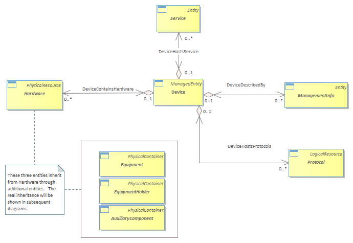
Figure PR.02 - (PR.04, PR.05) - Different Aspects of a Device - Illustrative : Class diagram
<b>A Starting Point – Supporting Basic Inventory Concepts</b><br/>Let’s start by categorizing the key entities that need to be modelled:<br/> • Equipment, such as Routers and Switches (for now, this document is focused on chassis-based devices)<br/> • Equipment components, such as line cards<br/> • Equipment “containers”, such as racks and chassis<br/> • Location of the Equipment (e.g., a Router is in this rack in this wiring closet…)<br/> • Location of a physical item within an Equipment (e.g., ability to distinguish between different physical ports on different cards of a Router)<br/> • Important auxiliary Equipment (e.g., cables, connectors, and power supplies) that are necessary for the correct operation of the Equipment<br/>The idea of Equipment containers that can contain Equipment is modelled using three concepts. Fundamental to this is the need to have separate classes to model Equipment and containers of Equipment. We accomplish this by defining two separate classes, called Equipment and EquipmentHolder. While this models the different type of object categories that we need, what we haven’t yet done is model how Equipment is contained in an EquipmentHolder. This is done using the EquipmentInHolder aggregation.<br/>It is important to know and keep separate the different states that Equipment can exist in. For example, consider the LineCard mentioned above. The function of the LineCard is (for example) to provide routing and forwarding of packets. This means that a LineCard cannot exist in the ether – it must interact with other elements (e.g., the other components of a Router, of which the LineCard is but one component) and therefore must be contained by a type of EquipmentHolder. However, LineCards can exist outside of being installed in an EquipmentHolder – as spares or as part of a kit that is yet to be built in inventory storage, for example. This model is concerned solely with modelling the physical composition of Network Devices. Thus, it will view Equipment and EquipmentHolders in this light, and concentrate on developing a model of physical equipment that satisfies the use cases mentioned earlier. While identifying a spare LineCard is of course very important, that identification is not done as a formal part of this model. However, it can be easily constructed as an extension of this model (or as part of a new model) using this model and the Location model (and possibly others as needed). Note that the Location model can be used to provide a physical description of where an object is.<br/>Back to the EquipmentInHolder relationship, the multiplicity of this relationship is 0 or 1 on the aggregate side, and 0 or more on the component side. The “0” on the aggregate side means that this aggregation is an optional relationship and does not need to be instantiated. This makes sense, because it is certainly possible to have a rack (a type of EquipmentHolder, as we will see) and a Router (a type of Equipment) that are both sitting in an inventory shelf prior to installation. In this case, the router is not yet installed into the Rack, and therefore this aggregation does not yet exist. However, if the EquipmentHolder is being used (the “1” part of its cardinality) then it may contain 0 or more Equipment. The cardinality of 0 or more is important, because it reflects the process of first installing the EquipmentHolder and then populating it with one or more Equipment.<br/>(Note that we could have implemented this as 0..* on both sides of the relationship. The motivation for this, of course, is to be able to use the model to represent time variances (past, present and future states). Remember, however, that this represents a “current state” model. Time variance can be accommodated by providing multiple instances of this state model, one each to represent different time periods. The other problem with 0..* on the EquipmentHolder side of the relationship is that this means that any Equipment can be put in any EquipmentHolder, which is clearly wrong. We can constrain the relationship using EquipmentSpecifications, which will be described later in this document.)<br/>When Equipment, such as our LineCard above, are not installed in an EquipmentHolder, then the EquipmentInHolder relationship is not instantiated, and the Location model takes over, driving the description of where the LineCard is currently located. When the LineCard is installed in an EquipmentHolder, then the position of the LineCard relative to its containing EquipmentHolder is determined by this model. The Location model is still useful, and for example provides the physical location of the Equipment that the LineCard is a part of. However, it does not provide the physical location of the LineCard within its containing EquipmentHolder.<br/>We notice that the multiplicity of EquipmentHolder, Equipment, and EquipmentComponent on the HolderLocatedAt, EquipmentLocatedAt, and ComponentLocatedAt associations, respectively, is 0..n. This reflects the fact that each of these objects can exist at multiple locations. The cardinality at the Location end for each of these three associations is 0..1, meaning that if this (optional) association is instantiated, it specifies a particular Location that an EquipmentHolder, Equipment, or EquipmentComponent is located at. Again, it is important to remember that if the respective cardinalities of these associations was “1” instead of “0..1”, then that would mean that this entity must be instantiated. That is why these cardinalities all have a “0” component (to indicate their optional behavior).<br/>The above is a lot of detail. It was felt that one example was needed to orient the reader. Note that for brevity, this version of this Addendum will not provide the amount of detail on each relationship and object as was just provided above. However, similar thinking processes were used to construct these other relationships and objects.<br/>Examples of EquipmentHolders include Racks and Chassis. Each of these can have other components attached to them (e.g., fans, cable ducts, cards, and so forth). We’ll represent this set of entities by the generic name “EquipmentComponent” for now – the real class hierarchy is more complicated and will be developed later in this Addendum. Given this type of Equipment, we see that it can be attached to EquipmentHolders as well as Equipment. Thus, we need two additional compositions – ComponentInHolder and ComponentInEquipment – to represent these relationships. Since EquipmentComponent is the entity that is being associated with another entity, both of these relationships define the cardinality on the EquipmentComponent side to be *. Similar to the above reasoning, both of these relationships define the cardinality on the EquipmentHolder and Equipment side to be 0..1.<br/>Note that other parts have also been simplified. For example, in reality, EquipmentHolders can of course contain Equipment as well as other EquipmentHolders – think of the case where a Chassis is contained inside of a Rack. Both a Chassis and a Rack are EquipmentHolders. Details such as these were deliberately left off in order to keep the diagram at this introductory stage of this Addendum as simple as possible. These details will be added into the final model later in this document.<br/>The final part of this first preliminary model is to realize that every object has a physical location. Some applications do care about the exact physical location of every physical object, while others are content to abstract this into a physical location for the overall Equipment and perhaps physical references to key components of the Equipment (e.g., this physical Port is on this physical Card located in this Slot). Therefore, we’ve identified three generic associations – HolderLocatedAt, EquipmentLocatedAt, and ComponentLocatedAt – that represent this capability. We’ll consolidate this as we develop the class hierarchy throughout the remainder of this section.<br/><br/><b>Equipment Requirements In More Detail</b><br/>Equipment is at the core of the overall SID model. As such, there are two distinct requirements that Equipment must meet. First, it must be easy to differentiate who owns and administers the Equipment. Otherwise, the Equipment will not be properly accounted for, let alone managed. Second, it is important that customers as well as Service Providers be able to express their needs clearly in order to determine which Equipment can support their requirements.<br/>In the SID, the Party Model (defined in Common Domain guide book) is used to describe people as well as organizations. Ownership is represented by a Party playing a particular role. Thus, we will use an association to relate an instance of the PartyRole class to an instance of the Equipment class.<br/>However, this brings us up against a conceptual problem: how do we classify Equipment? Remember that the business person wants to use concepts such as Router, Switch, Firewall in addition to different types of cards, chips, and auxiliary components, such as fans and power supplies. Clearly, we need to start working on a hierarchy that supports the concept of different types of Equipment.<br/>The objects that we’ve just described lend themselves to classification using three different categories:<br/>“Devices”, such as Routers, Switches and Firewalls, that perform one or more end-user functions<br/>“Device Components”, such as LineCards and chips, that fit into the Device and are managed components; these objects are directly needed by the Device to perform its primary end-user function(s)<br/>“Auxiliary Components”, such as power supplies and fans; that are required for proper operation of the Device but have a function that is different than the primary end-user function(s) of the Device.<br/>A “Device” is a managed entity that exists in a single physical structure, or “box”. Clearly, a managed entity such as a Router can be a very complicated device, having its functionality supplied by multiple LineCards that it contains. However, it is still important to be able to refer to either the “Device” as a whole or to individual components of the Device (e.g., a PhysicalPort of a particular LineCard in the Device).<br/>Device Components and Auxiliary Components don’t form a complete function on their own – rather, their purpose is to support the function(s) performed by their containing Device. However, the functionality of Device Components is directly related to the primary purpose of the device, whereas the functionality of the Auxiliary Component isn’t. For example, a LineCard is a type of DeviceComponent because it supplies routing and forwarding functions, which are related to why one uses a router and not some other type of device. A power supply is an AuxiliaryComponent because while power is clearly required by a router, power is not one of the salient characteristics that differentiate a router from other types of Devices.<br/>The SIM tends to define Devices, as described above, as logical components. However, from an inventory point-of-view, a Device usually corresponds to a single physical “box” that is located somewhere. (Alternatively, a Device could correspond to multiple physical boxes. This gets interesting, because oftentimes such a Device appears as a single logical entity, even though it consists of multiple physical entities. An example is a “stackable” switch, which consists of multiple physical switches that can be connected so that they appear to be a single Device to the network). The challenge is to be able to assign one or more locations to the physical box(es) that correspond to the Device.<br/>By providing an entity to represent the physical manifestation of the Device, we can not only track changes to its location, but we can also directly relate the physical manifestation of a router with its logical components (we need the System View of the Physical Resource model to do this)..<br/>An example will help to make this clearer. Consider a Router. People think of a Router as a Device in its own right. However, a Router is in actuality a very complex object, having many components and concepts that exist as managed objects.<br/>Some of these objects are shown conceptually in the following Figure. The reader will notice that all but Hardware and AuxiliaryComponent (which represents the “Device Components” and “Auxiliary Components” categories, respectively, from the above description) are logical in nature. The focus of this Addendum is, of course, on the physical aspects of a Device. However, we must be cognizant of the other major entities, so that we have the correct set of classes defined to facilitate relating these logical concepts to the appropriate objects in the physical model. The logical concept of a “Router” is really the collection of the different aspects of a Router, some of which are shown below (note that “Device” in the figure below represents physical and logical components).<br/>In the figure below, the “Device” is the “center of the universe”. It is the entity that provides functionality. From the point-of-view of this Addendum, this functionality takes the form of being the physical basis for:<br/> • hosting services (conceptually represented by the DeviceHostsService aggregation – this is developed more in this Addendum and in Addendum GB922 Service)<br/> • hosting protocols (represented by the DeviceHostsProtocols aggregation)<br/> • containing hardware, which is the main subject of this Addendum<br/>The first three aggregations represent that services, and protocols (which are all logical entities) all require a physical medium to run on. The fourth aggregation enables us to focus on the physical composition and characteristics of a device.<br/>Devices also are the physical basis for hosting different types of management information, such as alarms, statistics, and so forth. This is represented by the DeviceDescribedBy aggregation. ManagementEntity is the superclass for representing entities that represent management information obtained in a managed environment. Specifically, in the process of managing an entity, information of various forms are created. ManagementEntity is the base class for defining and representing different types of management information.<br/>
|


